Quantum Circuit Equivalence Checking#
Consider a quantum circuit \(G=g_0\dots g_{|G|-1}\) acting on \(n\) qubits. Each gate \(g_i\) of \(G\) is described by a corresponding unitary matrix \(U_i\) that is subsequently applied during the execution of the quantum circuit. Thus, the functionality of the circuit \(G\) can be obtained as a unitary system matrix \(U\) itself by computing \(U=U_{|G|-1}\dots U_0\).
The equivalence checking problem for quantum circuits can be defined as follows:
Given two quantum circuits \(G=g_0\dots g_{|G|-1}\) and \(G'=g'_0\dots g'_{|G'|-1}\) acting on the same set of qubits, do they realize the same functionality? More specifically, does it hold that \(U=e^{i\theta}U'\) or, equivalently \(UU' = e^{i\theta} \mathbb{I}\), where \(\theta\in(-\pi,\pi]\) denotes a physically unobservable global phase?
Conceptually, checking the equivalence of two quantum circuits is as simple as constructing and comparing the respective system matrices. However, the size of these matrices grows exponentially with the number of qubits, which quickly renders straight-forward methods (such as arrays) infeasible. Equivalence checking of quantum circuits has even been shown to be QMA-complete.
QCEC provides several complementary methods for efficiently tackling this challenging problem—each with their respective use cases, capabilities, and drawbacks.
Construction Equivalence Checker (using Decision Diagrams)#
While the underlying matrices are exponentially large with respect to the number of qubits, they frequently are sparse or contain inherent redundancies. Decision diagrams have been proposed as a means to exploit these redundancies. For a detailed intro to this topic, see [1] and the references therein. In many cases, using decision diagrams allows to obtain polynomially-sized representations for the otherwise exponentially large system matrices—in the best case even linear.
The functionality of both circuits is constructed by subsequently multiplying the decision diagrams representing the individual gates of \(G\) and \(G'\)—until, eventually, decision diagram representations for the system matrices \(U\) and \(U'\) are obtained. Since decision diagrams are canonical representations of the underlying matrices, checking the equivalence of both circuits can be reduced to comparing the root pointers of the resulting decision diagrams.
Most effective for: proving equivalence or non-equivalence of circuits whose functionality is sparse and/or contains redundancies.
Capable of showing: equivalence and non-equivalence
Drawback: Decision diagrams might still be exponentially large in the worst case.
Alternating Equivalence Checker (using Decision Diagrams)#
Due to the inherent reversibility of quantum computations, equivalence checking of two circuits \(G\) and \(G'\) can also be reduced to proving that the composition of one circuit with the inverse of the other implements the identity, i.e., \(G^{\prime -1} G = \mathbb{I}\). While the identity is represented by a decision diagram of linear size, sequentially constructing the representation for \(G^{\prime -1} G\) still constructs the (potentially exponentially large) representation of one of the circuit’s system matrix along the way.
The main idea is to, instead, start with the identity \(\mathbb{I}\) in between both circuits, which is symbolized by \(G \rightarrow \mathbb{I} \leftarrow G'\). Then, gates from either circuit are applied in an alternating fashion according to some application scheme, with the goal of staying as close as possible to the identity. Given that a suitable order of execution can be determined, an efficient representation can be maintained throughout the entire verification process.
For further information on this method, see [2].
Most effective for: proving equivalence of two circuits sharing a common structure, e.g., one circuit being a compiled or optimized version of the other.
Capable of showing: equivalence and non-equivalence
Drawback: Performance depends on the availability of a suitable application scheme or oracle for predicting when to apply gates from either circuit.
Simulation Equivalence Checker (using Decision Diagrams)#
It has been shown in [2], that even small differences in quantum circuits frequently affect the entire functional representation due to the reversibility of quantum computations. As a consequence, simulating both circuits with a couple of arbitrary input states, i.e., considering only a small part of the whole functionality, provides an attractive alternative to the methods described above.
In [3], several types of states have been proposed that allow to trade off efficiency versus performance:
Classical stimuli (i.e., random computational basis states) already offer extremely high error detection rates in general and are comparatively fast to simulate, which makes them the default.
Local quantum stimuli (i.e., random single-qubit basis states) are a little bit more computationally intensive, but provide even better error detection rates.
Global quantum stimuli (i.e., random stabilizer states) offer the highest available error detection rate, while at the same time incurring the highest computational effort.
Most effective for: quickly detecting non-equivalence, even in cases where both circuits only differ slightly.
Capable of showing: non-equivalence
Drawback: Decision diagrams for state vectors might still be exponentially large in the worst case.
ZX-Calculus Equivalence Checker#
In [4], Kissinger and van de Wetering proposed an algorithm for optimizing quantum circuits based on ZX-calculus rewriting. In their initial article they also show that this rewriting approach can be used to prove the equivalence of quantum circuits. The idea is to construct the ZX-diagram of \(G^{\prime -1} G\) and reduce this ZX-diagram using the rules of the ZX-calculus until no further rewrites can be made. If the resulting diagram consists only of wires (the identity ZX-diagram) then \(G = G^{\prime}\). This approach has been extended in [5] to also handle ancillary qubits, floating point inaccuracies in gate parameters, as well as permutations of input and output layouts of quantum circuits.
In [6], it has been shown that equivalence checking with the ZX-calculus naturally complements equivalence checking with decision diagrams. Since the size of the ZX-diagram during rewriting is bounded by the size of the initial diagram, this checker can be easily executed in parallel to the aforementioned approaches based on decision diagrams. In cases where the size of the decision diagrams explodes, the rewriting approach can often prove equivalence much more efficiently.
Most effective for: proving equivalence of two circuits involving many rotation gates with angles of the form \(\frac{\pi}{k}\) for \(k\in\mathbb{N}\).
Capable of showing: equivalence
Drawback: Due to the incompleteness of the rewriting rules, this equivalence checker cannot prove non-equivalence. Furthermore, multi-controlled gates have to be decomposed prior to the equivalence check, which can quickly lead to large ZX-diagrams and slow runtimes.
Resulting Equivalence Checking Flow#
QCEC implements and expands upon the flow proposed in [2] as illustrated in the following figure that orchestrates all the above equivalence checkers.
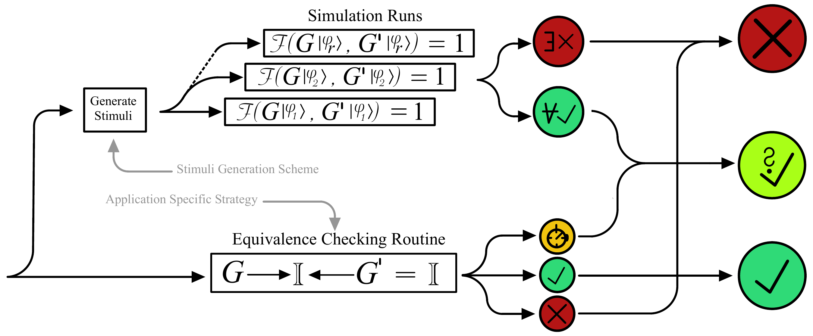
In general, the following steps are performed:
First, a couple of simulation runs with random computational basis states are started. Should any of these simulations show a difference in the resulting states, the check is finished.
In parallel, the alternating equivalence checker is started. In case the check finishes, i.e., it does not run into a timeout, a definitive result is returned. Otherwise, if none of the simulations have shown a difference, this strongly indicates that both circuits are probably equivalent.
In addition to the above, the ZX-calculus equivalence checker is started. In case it finishes with an affirmative answer, the check is finished. In case it finishes and was not able to reduce the ZX-diagram to the identity, this indicates that the circuits are probably not equivalent.